Alignment
Terminology: Alignment vs Calibration
JS-50 ScanHeads come calibrated from the factory. In our production process, we determine the relationship between the laser line, the housing and the image sensor and program the results into the firmware on each head. That means when you take a ScanHead out of the box, hook it up and start scanning, it will give you X-Y coordinates in a cartesian coordinate system right away. A scanned circular object has the correct diameter, and points on a flat object have the correct distance from each other.
How this cartesian coordinate system is related to the scanner housing is fixed, so you can replace one scanner with another and the data will be in the same place. We don't, however, publish the exact orientation (shift and rotation) of this system with respect to the housing. As we improve our processes, we may change these values, and have done so in the past.
Alignment is the term that describes how the coordinate system of one ScanHead is related to the real world, i.e. the machine center it is used in, and thereby also to any other scanners. On multi-head systems, Alignment is used to bring all individual coordinate systems into a common reference frame, something we call the Mill System. Things are so much nicer when you can treat all points from all ScanHeads the same, and with a bit of clever alignment, measuring values along the coordinate axes of the mill system becomes trivial. As an example, if you align your ScanHead(s) such that the origin of the mill system coincides with the top of belt/chain, then board thickness is simply the Y value of a point!
- Summary
- Calibration is done at the factory and will not change, Alignment must be done by you at the installation site; and transforms your point data into a common Mill System.
We won't be mad at you for using the terms interchangeably, but within this documentation we will only talk about Alignment.
Alignment Parameters
By adjusting the Alignment Parameters, it is possible to change how scan data is presented to the end user from each individual ScanHead. This is commonly used to have all of the ScanHeads to have a common coordinate system that is referenced to the mill machinery (the Mill System), such as having the Y axis be plumb vertical with Y = 0 set to the top of the chain/belt and X = 0 being at the middle of the chain/belt.
The following parameters are presented to the end user through the API:
- Roll
- Rotates the data by a specified number of degrees.
- Shift X
- Offsets the X axis by a given distance (in ScanSystem units)
- Shift Y
- Offsets the Y axis by a given distance (in ScanSystem units)
- Orientation
-
Flips the X axis if a given JS-50 ScanHead is oriented 180 degrees differently from other ScanHeads within a system.1 The default orientation of the JS-50 is shown below; this is referred to as being "cable upstream"2.
WX, MX and WSC Default "Cable Upstream" X6B, Z8 Default "Cable Upstream" 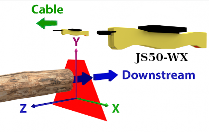
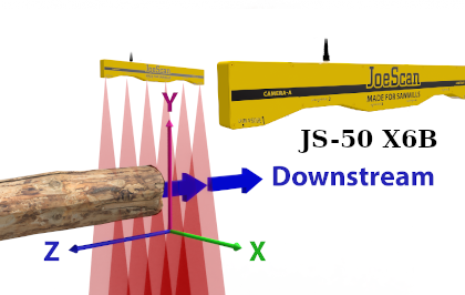
right-handed coordinate system right-handed coordinate system
Alignment in JsSetup
Our configuration tool, JsSetup, offers a comfortable way of determining the Alignment Parameters for a ScanHead, using Fixtures. Please see the relevant page for the Alignment Workspace.
Alignment in the API
The Pinchot API is responsible for applying the Alignment Parameters to the received point data. Here are the relevant functions:
For camera-driven ScanHeads:
public void SetAlignment(Camera camera, double rollDegrees, double shiftX, double shiftY)
public void SetAlignment(Laser laser, double rollDegrees, double shiftX, double shiftY)
public void SetAlignment(double rollDegrees, double shiftX, double shiftY)
For camera-driven ScanHeads:
int32_t jsScanHeadSetAlignmentCamera( jsScanHead scan_head,
    jsCamera camera,
    double roll_degrees,
    double shift_x,
    double shift_y);
int32_t jsScanHeadSetAlignmentLaser( jsScanHead scan_head,
    jsLaser laser,
    double roll_degrees,
    double shift_x,
    double shift_y);
int32_t jsScanHeadSetAlignment( jsScanHead scan_head,
    double roll_degrees,
    double shift_x,
    double shift_y);
Difference to the JS-20/25 alignment
Our previous generation of scanners, the JS-20/25 line, stored the parameters on the scan heads themselves. Upon each reboot, the heads would restore a previously set alignment, and send data in the Mill System.
For the JS-50, the parameters are never sent to the ScanHead, instead, the API applies them before handing data to the consumer (your application).
The consequence is that for the JS-50, you are responsible to set the parameters before you start scanning. If not set, the scanners will still deliver data, but each in their own coordinate system, which is most likely not what you want!
Alignment for Camera-Laser-Pairs
So far, in this section, we only talked about a set of Alignment Parameters and how it applies to a ScanHead. This is actually not the whole truth: because most of our models (with the exception of the WSC and the MX) have more than one camera or more than one laser, we need to have a set of Alignment Parameters for each Camera-Laser-Pair. The Pinchot API does contain functionality to set an Alignment for an entire ScanHead for compatibility with older software, but the functions are marked as obsolete and will be removed in a future version.
For JS-50 WX models, please also see this Technical Note.
-
This is common to facilitate better cable routing. Note that there is no preferred orientation, as long as you set the correct value for each ScanHead in a group, no other effects will be noticeable. ↩
-
the terms upstream and downstream were chosen to indicate an orientation with respect to the flow of material in e.g. a sawmill, where boards or logs flow in a stream in a fixed direction. ↩