Exclusion Mask Editor
Overview
Exclusion Masks are an advanced concept in JsSetup. The Pinchot API provides for the capability to mask out certain areas of the image sensor, preventing measurements therein. This can be helpful in situations where the one or more cameras see a bright light source that overpowers the laser light.
The difference to Scan Windows is that Scan Windows are always defined in Mill Space (i.e. the final coordinate system that measured profiles are delivered in), whereas Exclusion Masks work in Sensor Space (i.e. the camera image).
Generally, Exclusion Masks are the tool of last resort, if stray points can not be avoided by applying a Scan Window. The two features can be used together, however, Exclusion Masks are applied earlier in the processing pipeline on the ScanHead and will take precedence over Scan Windows.
Differences between JsSetup and Pinchot API
JsSetup defines Exclusion masks as rectangular areas with a Top/Left/Height/Width property. All sensor pixels within the enclosed area are masked out, i.e. will be disregarded in the measurement process. The Pinchot API provides a "per-pixel" bitmap mask, where individual pixels can be excluded. JsSetup translates the rectangular areas defined by the user to a bitmap mask on the fly when computing the preview, but stores the areas as discrete rectangles in the ScanSystem definition file. The provided parsers do the same, they render the rectangular mask areas into a bitmap the API can ingest.
Future versions of the Pinchot API may add rectangular Exclusion Masks.
User Interface
Toolbar
The toolbar contains the following items:
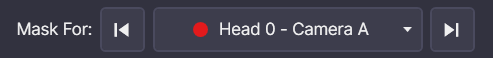
Camera-Laser-Pair Selector
This dropdown allows the user to select the Camera-Laser Pair for which the exclusion mask is to be defined. The dropdown is populated with the Camera-Laser Pairs defined in the ScanSystem.
Editing Mode Buttons
The following buttons are available for editing the exclusion mask:
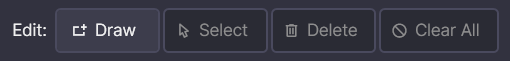
- Draw: This button allows the user to draw a new exclusion mask. Click and drag to draw a rectangle. The rectangle will be shown with a hatched yellow fill. You can draw multiple rectangles, even overlapping ones. The preview will show the combined effect of all masks.
- Select: In this mode, you can select existing mask rectangles. Click on multiple rectangles to select them. You can then delete them, using the Delete button.
- Delete: This button deletes the selected mask rectangles.
- Clear All: This button deletes all mask rectangles.
Exposure Control
This control has two states: Laser View and Camera View. The user can switch between these two views to see the effect of the exclusion mask.


You can switch between the two views by checking/unchecking the Laser View checkbox. The Camera View is helpful for identifying areas where the camera sees a bright light source that overpowers the laser light.
You can also adjust the exposure time for both views using the slider.
Accept/Revert Buttons
The Accept and Revert buttons allow the user to accept or revert the changes made to the exclusion mask.