Field of View
For each JS-50 model, we publish a data sheet including the usable Field of View. During factory calibration, we establish the geometric relationship between each pixel in image sensor space and real world coordinates.


| A (mm) | B (mm) | C (mm) | D (mm) | |
|---|---|---|---|---|
| Far Distance | Near Distance | Far Width | Near Width | |
| WX | 1140 | 350 | 1270 | 380 |
| WSC | 1140 | 350 | 1270 | 380 |
| MX | 2130 | 510 | 1040 | 250 |
| X6B20 | 3050 | 2290 | 910 | 690 |
| X6B30 | 2440 | 910 | 1220 | 480 |
| Z820 | 3050 | 2290 | 910 | 690 |
| Z830 | 2440 | 910 | 1220 | 480 |
| A (inch) | B (inch) | C (inch) | D (inch) | |
|---|---|---|---|---|
| Far Distance | Near Distance | Far Width | Near Width | |
| WX | 45 | 14 | 50 | 15 |
| WSC | 45 | 14 | 50 | 15 |
| MX | 84 | 20 | 41 | 10 |
| X6B20 | 120 | 90 | 36 | 27 |
| X6B30 | 96 | 36 | 48 | 19 |
| Z820 | 120 | 90 | 36 | 27 |
| Z830 | 96 | 36 | 48 | 19 |
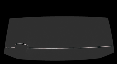
Due to a number of factors, including lens distortion and our method of calibration, the shape of this area as seen from the camera sensor is not a perfect trapezoid, instead, it may have curved boundaries:
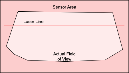
Relationship of Field of View, Sensor Area and Laser Line
During manufacturing, the sensor and laser are aligned such that the full extent of the laser line is visible on the sensor. The Actual Field of View is the region in which the ScanHead is calibrated. The Spec Sheet Field of View is guaranteed be be contained in the Actual Field of View.
The laser line will always cover the Actual Field of View.
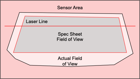
All JS-50 may deliver data outside the Spec Sheet FOV (but inside the Actual FOV), however, the accuracy of those points is not guaranteed. In production systems, you should no rely on data collected outside the Spec Sheet FOV.
In JsSetup, you can visually verify the FOV by going to the Exclusion Masks workspace. You will see the outline of the Field of View in sensor space, as shown above.