Exposure
In this section, we discuss how to set up exposure times. We give detailed information on how to optimize exposure settings, improving data quality and accuracy.
Background
In order to understand how the JS-50 exposure settings affect measured data, a little background is necessary.
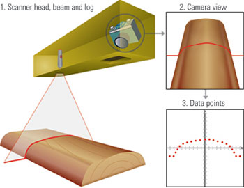
The JS-50 ScanHeads project a laser line onto the object to be measured, and record the resulting image with a camera. The camera image is analyzed column by column, and the intersection point of the laser line for each column is determined. Leaving aside a number of other contributing factors, the measurement comes down to the accurate determination of the center of the laser line in the image.
Camera Exposure Time
A common question for new users of the JS-50 family is how Camera Exposure Time and Laser On Time relate.
The main operational parameter for production use of the scanners is Laser On Time. The firmware on the heads controls how long the laser diode is on, and automatically adjusts the time the image sensor is "open" based on that value. The API provides functions to set the Laser On Time via a configuration object:
public class ScanHeadConfiguration {
    public uint MinLaserOnTimeUs { get; private set; }
    public uint DefaultLaserOnTimeUs { get; private set; }
    public uint MaxLaserOnTimeUs { get; private set; }

    public uint MinCameraExposureTimeUs { get; private set; }
    public uint DefaultCameraExposureTimeUs { get; private set; }
    public uint MaxCameraExposureTimeUs { get; private set; }
    // ... abbreviated
}
typedef struct {
uint32_t laser_on_time_min_us;
uint32_t laser_on_time_max_us;
uint32_t laser_on_time_def_us;

uint32_t camera_exposure_time_min_us;
uint32_t camera_exposure_time_max_us;
uint32_t camera_exposure_time_def_us;

// ... abbreviated
} jsScanHeadConfiguration;
 It is important to know that the Camera Exposure Time is only used for diagnostic images, i.e. images where you are interested in the image content, for e.g. diagnostic purposes. The Camera Exposure Time is not relevant for the point measurement process.
In future versions of the API, we will remove the Camera Exposure values from ScanHeadConfiguration/jsScanHeadConfiguration to make the distinction clear.
Laser On Time and Exposure
Three primary parameters and three secondary parameters influence the exposure algorithm, ultimately determining the length of time the laser is active and the time the camera shutter is open. You can either choose a fixed time or let an algorithm determine the optimum time, based on the parameters.
Fixed Exposure vs. Automatic Exposure
The most important factor for high quality measurements is the amount of reflected laser light hitting the camera sensor. Darker objects (e.g. bark or tropical woods) reflect less light and need longer exposure times than lighter objects. However, in practice it rarely is the case that all scanned objects have the same reflectance: the natural variation of a material like wood leads to varying exposure requirements.
The JS-50 ScanHeads have an inbuilt auto-exposure algorithm to correct for this. A short feedback loop can change the Laser On Time, based on the amount of light received in a scan. This algorithm operates within bounds set by the parameters detailed below.
The algorithm can be disabled by simply setting all parameters to the same, fixed value, thus effectively forcing the ScanHead to operate with a single Laser On Time. There are advantages and disadvantages to both approaches. In the following sections we want to detail how the algorithm works, so you can make a decision which approach is better for your scanning application.
Primary Parameters
Minimum Laser On Time, Default Laser On Time and Maximum Laser On Time
| Parameter | Description | min Value | max Value | default value |
|---|---|---|---|---|
| Minimum Laser On Time | Lower Bound of the autoexposure algorithm | 15 μs | Default Laser On Time | 100 μs |
| Default Laser On Time | Starting value of the autoexposure algorithm | Minimum Laser On Time | Maximum Laser On Time | 500 μs |
| Maximum Laser On Time | Upper Bound of the autoexposure algorithm | Default Laser On Time | 10000 μs | 1000 μs |
So, as an example, setting 100/100/100 for minimum, default and maximum will disable the autoexposure algorithm and always expose for 100μs.
Setting 15/100/200 will enable the autoexposure algorithm, and let it vary the exposure time from 15μs to 200μs. We will look at how the algorithm works and how to find optimal bounds further down.
Secondary Parameters
These parameters only make sense in the context of the autoexposure algorithm, and rarely need to be changed from the defaults. We will
- Laser Detection Threshold
-
Determines how bright a given camera region needs to be in order to trigger a valid data point. A lower value implies that data points will be generated with less light exposure and a higher value will require more light exposure for data to be generated.
- Saturation Threshold
-
Sets the brightness required in order to consider a given data point to be considered saturated. Once enough points are saturated, auto exposure will then drive the laser on time down in order to reduce the number of points that are saturated. Similarly if not enough of the points are saturated, auto exposure will then drive the exposure time up.
- Saturation Percentage
-
The percentage of data points returned within a given profile that are required in order to determine if the profile is sufficiently saturated. If over saturated this will engage auto exposure to drive the saturation down; similarly if under saturated auto exposure will then engage to drive the saturation up.
The Autoexposure Algorithm
The parameters above are inputs to the autoexposure algorithm. Let's take a look at how the code works and what happens when the API tells the scanner to start scanning:
- The first exposure is done with the Default Laser On Time
- The algorithm evaluates how many valid data points could be measured, using the Laser Detection Threshold
- If no points at all were measured, that's already the end of the loop - the exposure time will stay set at default.
- If some points are measured, the algorithm counts the data points that are "saturated" (i.e. above the Saturation Threshold) and with that count, also the percentage of saturated points.
- Evaluating the percentage of "saturated" points against Saturation Percentage, the algorithm will now drive the LaserOnTime (exposure) up or down for the next scan, and thus repeat this loop. It will stop adjusting when
- Minimum Laser On Time is reached when adjusting downwards,
- Maximum Laser On Time is reached when adjusting upwards,
- Saturation Percentage is reached. This is the "happy path".
There are a number of things to keep in mind when using AutoExposure. Here are some guidelines:
- Don't worry too much
-
Thankfully, the range of acceptable exposure values is quite large, and good measurements can be made even under adverse circumstances.
- Start with the defaults
- The presets for exposure in the Pinchot API will likely work for 99% of all use cases. You should not optimize exposure settings until all other settings have been dialled in.
- Shorter is better
- As one of the two big factors limiting the scanning speed (the other factor being Windowing), the Maximum Laser On Time will directly affect the achievable system scan rate. Phase durations [TBD] are calculated from the Maximum Laser On Time of all constituent elements, e.g. if the Maximum Laser On Time for a ScanHead is set to 3000μs, then any phase containing this ScanHead with be at least 3000μs long. On a system with six phases this leads to a minimum Phase Table length of 18ms (resulting in a 55 Hz scan frequency). Reducing the Maximum Laser On Time to 1000μs, we can reach 6ms Phase Table length (167 Hz scan frequency.) This example is somewhat simplified, but illustrates the effect of long exposure values.
Evaluating the results of AutoExposure
The first step in the evaluation is to put a representative object in the Field of View, under conditions similar to a production environment, e.g. at the same distance and the same ambient light. You can use JsSetup to get a live preview of your changes.
- Using the default values (100/500/1000), observe where the effective LaserOnTime ends up.
- LaserOnTime (as displayed in JsSetup) remains at Default
-
Not enough valid data points are found at the Default Laser On Time, and thus the algorithm does not adjust, neither up nor down. Increase the Default Laser On Time until you can see measured data points and the algorithm kicks in. In practice, this is a rare situation, but may indicate a different condition: a blocked camera or a defective laser both can trigger this behaviour.
- LaserOnTime is stuck at Minimum
-
This points to overexposure. You can lower the Minimum Laser On Time and see where the algorithm settles.
- LaserOnTime is stuck at Maximum
-
This points to underexposure. You can raise the Maximum Laser On Time and see where the algorithm settles. The Maximum Laser On Time can not be increased indefinitely without encountering some other effects (overall scan speed suffers, more noise is present). You should also check that camera and laser windows are clean and no obstructions are present.
Effect of Exposure Parameters on Scanning Speed
In a typical scanning system, multiple ScanHeads work in Phases, organized in a Phase Table. The API calculates the timing of each ScanHead's firing of lasers and cameras, so that no interference occurs. So, in essence, the scanning speed is determined by how quickly all Phases in the Phase Table can be executed - and that of course depends on how long the exposure of individual elements can maximally be.
Important
The Maximum Laser On Time is in most cases the limiting factor for scanning speed. The Pinchot API uses a very conservative value (1000μs). This means that a phase containing a ScanHead with the default value will occupy at least 1ms. In order to achieve maximum speeds, you should find out what exposure time will still give sufficient data points in the worst case (dark or wet wood, bark) and use this value as the Maximum Laser On Time. In JsSetup, the Exposure workspace lets you interactively explore the effect of different values.
Effect of Laser On Time on brightness values of measured points
In addition to the XY-coordinate of a measured point, the Pinchot API also provides the "Brightness" value.
What is the Brightness value?
Also termed "Laser Return Intensity" or similar, this value is a product of the measurement algorithm. In mathematical terms, it is the integral over the brightness distribution function centered around the brightness peak. In other words, it quantifies "how much light was returned to the pixels around the brightest spot".
The Brightness value is a good approximation of the visual appearance of the scanned object, and can be used to implement feature detection, with some important caveats:
- limited range: the Brightness value is covering only 6 to 7 bits out of the 8 bit range the API provides. That means that even when scanning a white object with a long exposure time at close distance, the peak value will rarely exceed 128.
- subject to fall-off and vignetting: due to the longer light travel distance to the outer pixels, directional reflectance, and camera vignetting, a pronounced fall-off towards the edges of the Field of View can be observed.
- does not scale linearly with exposure time.
The relationship of Laser On Time and Brightness value is not linear. If you intend to use the Brightness value for mosaicking or feature detection, you must correct for this. Finding the ideal combination of exposure, measurement accuracy and brightness is highly dependent on the local installation and can only be determined experimentally.
Beta Features in Pinchot API
As of v16 of the Pinchot API, you can use the Brightness Correction functions to correct an uneven brightness distribution. This functionality is currently in beta testing and may undergo breaking changes in upcoming releases. Please contact JoeScan support if you want to learn more.