Phase Table
The Phase Table is a component of the Pinchot API introduced at v16.0.0 that allows a programmer to schedule scanning in time among one or more scan heads without the risk of interference. When scheduling scan heads in the phase table, individual cameras and lasers, referred to as phase elements, are selected and placed within distinct phases in the phase table.
Lineal Scan System Example
Small Scan System
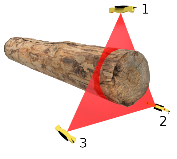
In the below example, three JS-50 WX scan heads, each with two cameras, comprise a single scan zone for a lineal system. Each JS-50 WX needs to be within its own distinct phase in order to avoid cross talk with the other scan heads that are looking at overlapping regions. Further, each camera is placed into its own phase to improve data density.
For this system, the phase table could be set up as follows.
| Phase | Position | Scan Head ID . Camera |
|---|---|---|
| 1 | Top | 1.CameraA |
| 2 | Bottom Right | 2.CameraA |
| 3 | Bottom Left | 3.CameraA |
| 4 | Top | 1.CameraB |
| 5 | Bottom Right | 2.CameraB |
| 6 | Bottom Left | 3.CameraB |
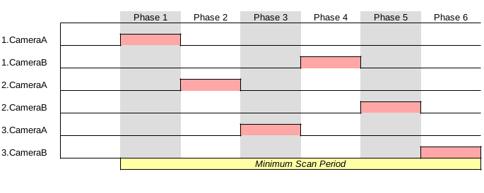
Assuming the laser on time is the same for all scan heads, the timing for the above phase table would have the following timing when scanning:
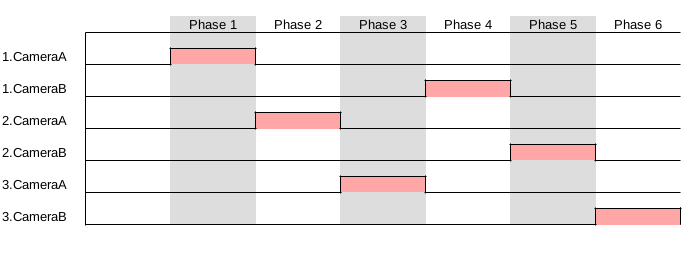
Upon completion of the last phase, (Phase 6 in this example), the phase table will start again at the beginning, (Phase 1), repeating the order of phases until the scan system is commanded to stop scanning.
Large Scan System
In this example, a total of 15 JS-50 WX scan heads are set up in a lineal system with five scan zones down the length of the log. The scan heads IDs are numbered such that they incrementing clockwise and moving downstream along the log.
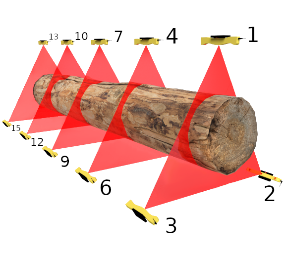
Multiple scanning elements can be placed into the same phase, allowing each to scan at the same time. For this example, there is no risk of cross talk due each phased element being in a different scan zone. One way to define the phase table would be as follows.
| Phase | Position | Scan Head ID . Camera |
|---|---|---|
| 1 | Top | 1.CameraA, 4.CameraA, 7.CameraA, 10.CameraA, 13.CameraA |
| 2 | Bottom Right | 2.CameraA, 5.CameraA, 8.CameraA, 11.CameraA, 14.CameraA |
| 3 | Bottom Left | 3.CameraA, 6.CameraA, 9.CameraA, 12.CameraA, 15.CameraA |
| 4 | Top | 1.CameraB, 4.CameraB, 7.CameraB, 10.CameraB, 13.CameraB |
| 5 | Bottom Right | 2.CameraB, 5.CameraB, 8.CameraB, 11.CameraB, 14.CameraB |
| 6 | Bottom Left | 3.CameraB, 6.CameraB, 9.CameraB, 12.CameraB, 15.CameraB |
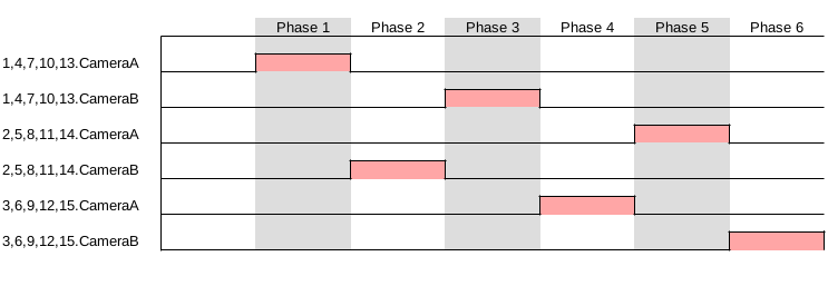
The timing for the above phase table configuration would be similar to the small scan system example, with the exception that each of the six phases would trigger scanning for all of the phased elements within it. Presented as a timing diagram, it would scan as the following:
Carriage Headrig Example
This example features six JS-50 X6B scan heads set up as a carriage headrig. Each scan head with its six lasers looks at a different section of the log. The scan head IDs increment from left to right.
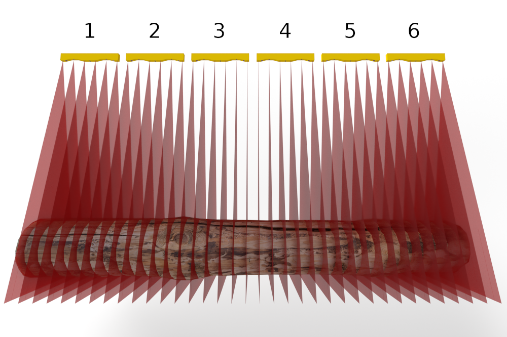
The lasers are spread across 12 phases to minimize cross talk. Odd numbered scan heads have their lasers grouped together within the phase table; similarly, even numbered heads have their lasers grouped together within the phase table. The phases alternate between lasers grouped with Camera A and lasers grouped with Camera B so as to avoid hardware time penalties.
| Phase | Scan Head ID . Laser |
|---|---|
| 1 | 1.Laser1, 3.Laser1, 5.Laser1 |
| 2 | 2.Laser1, 4.Laser1, 6.Laser1 |
| 3 | 1.Laser2, 3.Laser2, 5.Laser2 |
| 4 | 2.Laser2, 4.Laser2, 6.Laser2 |
| 5 | 1.Laser3, 3.Laser3, 5.Laser3 |
| 6 | 2.Laser3, 4.Laser3, 6.Laser3 |
| 7 | 1.Laser4, 3.Laser4, 5.Laser4 |
| 8 | 2.Laser4, 4.Laser4, 6.Laser4 |
| 9 | 1.Laser5, 3.Laser5, 5.Laser5 |
| 10 | 2.Laser5, 4.Laser5, 6.Laser5 |
| 11 | 1.Laser6, 3.Laser6, 5.Laser6 |
| 12 | 2.Laser6, 4.Laser6, 6.Laser6 |
This phase table would result in the following timing diagram assuming equal laser on time for all scan heads:

Creating a Phase Table
The Pinchot API offers functions for building the phase table. The following functions are presented in each API and can be utilized within your code:
public void ClearPhaseTable()

public void AddPhase()

public void AddPhaseElement(
uint id,
Camera camera)

public void AddPhaseElement(
uint id,
Camera camera,
ScanHeadConfiguration configuration)

public void AddPhaseElement(
uint id,
Laser laser)

public void AddPhaseElement(
uint id,
Laser laser,
ScanHeadConfiguration configuration)
int jsScanSystemPhaseClearAll(
jsScanSystem scan_system);

int jsScanSystemPhaseCreate(
jsScanSystem scan_system);

int jsScanSystemPhaseInsertCamera(
jsScanSystem scan_system, jsScanHead scan_head,
jsCamera camera);

int jsScanSystemPhaseInsertCameraConfiguration(
jsScanSystem scan_system, jsScanHead scan_head,
jsCamera camera,
jsScanHeadConfiguration cfg);

int jsScanSystemPhaseInsertLaser(
jsScanSystem scan_system, jsScanHead scan_head,
jsLaser laser);

int jsScanSystemPhaseInsertLaserConfiguration(
jsScanSystem scan_system, jsScanHead scan_head,
jsLaser laser,
jsScanHeadConfiguration cfg);
For specifics regarding any of the above functions, the API documentation should be consulted. Generally however, the procedure is as follows.
- Create phase
- Add all elements to be phased to the newly created phase
- Repeat steps 1-2 until all phases have been constructed
This process walks through the phase table, starting from Phase 1, creating each phase in order until all the required phases are generated.
General Configuration
Each phase will run as long as needed to ensure that all elements within it complete their scan as defined by their individual Maximum Laser On Time. Care should be taken when adding scan elements with varying laser on times as the element with the longest scanning time will set the overall phase duration.
The phase table implemented in the Pinchot API is designed such that all elements within a given phase end at the same time. An example of three different scanning elements with different max laser on times is given below.
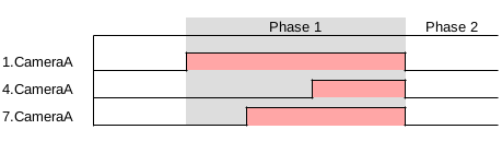
The entire duration of the phase table will be equal to the minimum scan period of the scan system. Choosing the minimum scan period when scanning with the scan system will ensure that there is no idle time where data is not collected. Selecting anything larger than the minimum scan period will pad extra time after the last phase where no data is collected.
Advanced Configuration
Care will be required when utilizing the same camera for multiple phases due to hardware limitations involving reading out data. Before the camera can begin collecting new data, data from the previous scan will need to be fully read out. This additional time constraint before the camera is ready to scan again is referred to as Readout Time.
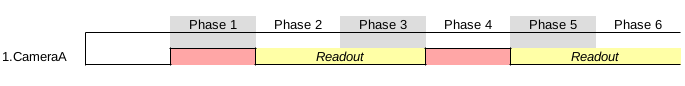
Readout time is greatly affected by the size of the Scan Window configured. A larger scan window will imply more data to be read from the camera and into software; conversely a smaller window will require less data to be read out. The Pinchot API will automatically handle the calculation of the additional readout time if it applies and adjust the phase times and minimum scan period appropriately.
The best approach to avoid delays due to readout time is to schedule phased elements that utilize the same camera either only once within the phase table or spaced out such that there are one or multiple phases in between reuse of the camera.