ScanSync and Encoder
ScanSync Module
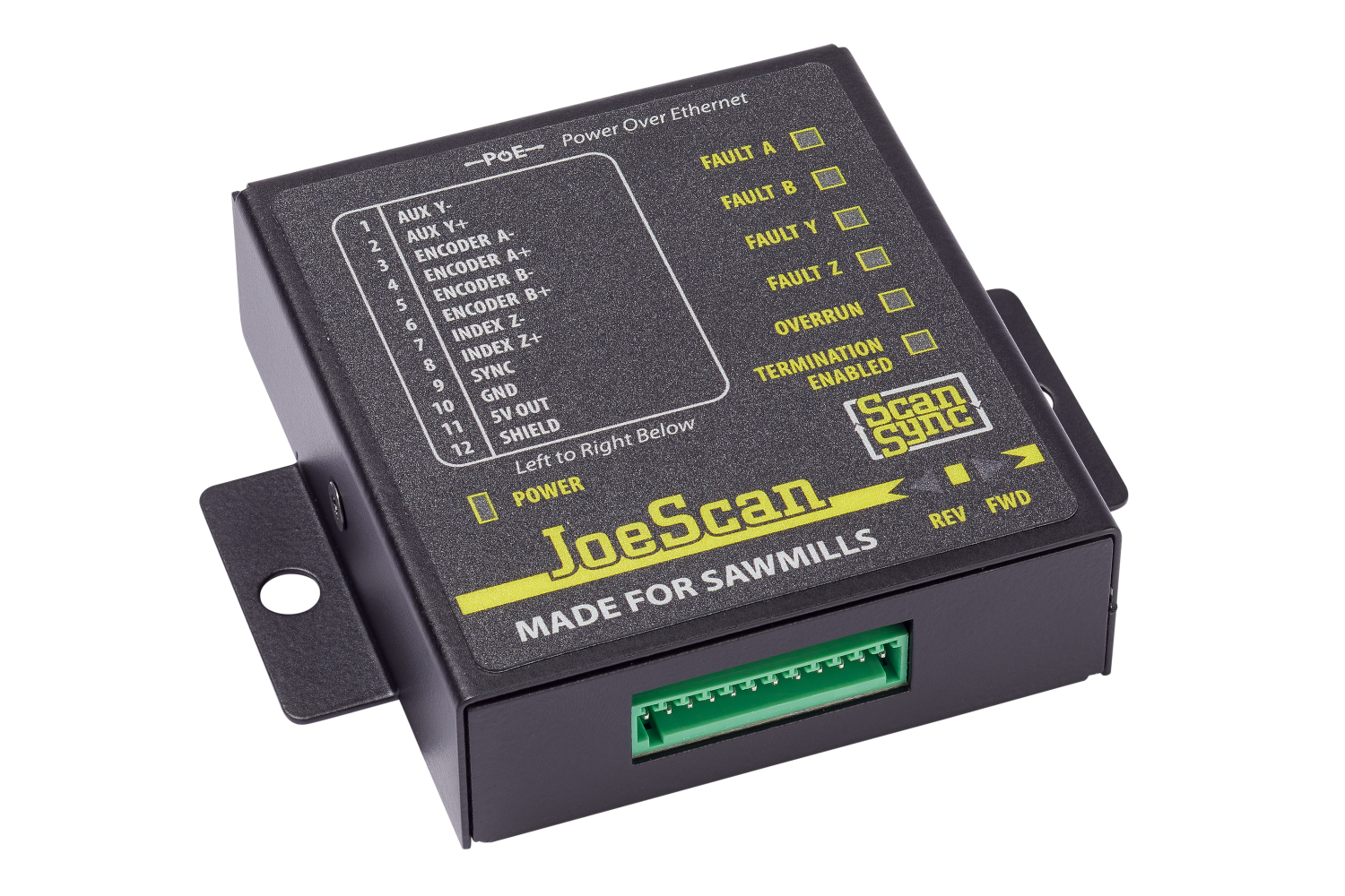
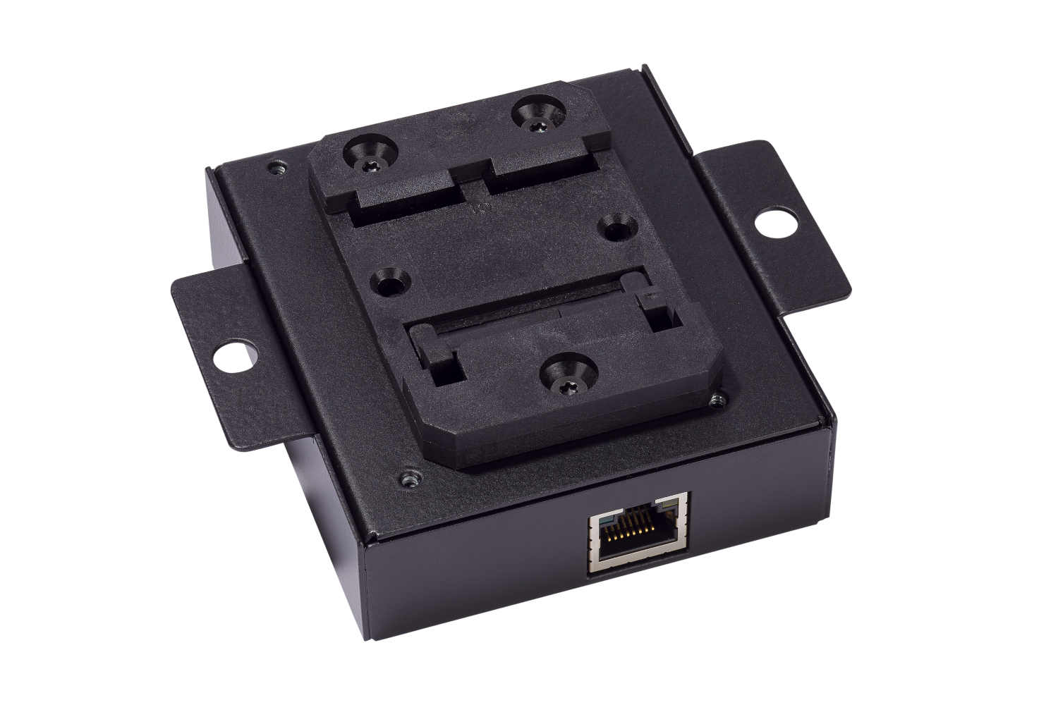
| Front | Back |
|---|---|
 |
 |
The ScanSync module acts as the master clock for the scanners in a system while also providing a means to communicate an attached encoder's position. All JS-50s on the same network will utilize the timing data from a ScanSync to synchronize their activities; this eliminates system timing issues that can occur if individual JS-50s are relying on their own internal clocks. This process is automatically performed and requires no intervention from the end user other than making sure that the ScanSync is on the same physical network as the JS-50 ScanHeads that are to be synchronized.
Input Signal Wiring
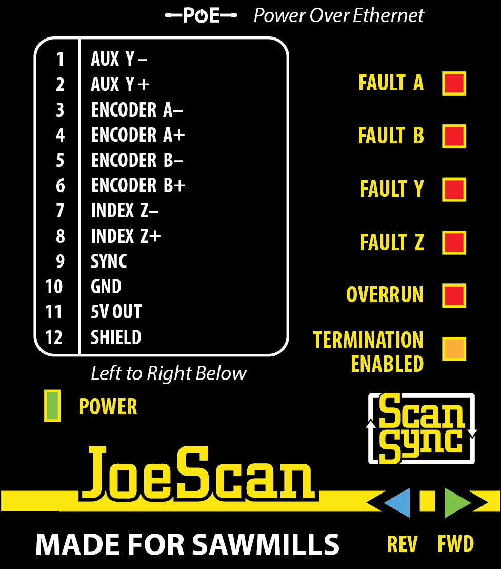
For reference, the wiring pin-out is printed on the housing.
Warning
As detailed in the section On Device Diagnostics, if the SCANSYNC status light on a ScanHead is illuminated (blue), then a reliable signal has been detected and scanning is possible.
However, the status light does NOT show if the encoder or aux inputs are available, for that we have to look at the device itself. Please refer to the sections below to check.
Mounting
The ScanSync module comes with a DIN Rail adapter installed. If needed, the adapter can be removed. The module also comes with tabs on either side as an alternative mounting option.
Power Supply
The module is PoE powered. Please see the Ethernet Switch page for more information on PoE requirements.
Terminal Block
The signals, power and input wires are connected via 12-pole terminal block. The connector is included with the module. Additional connectors can be obtained from e.g. Digikey: 12 Position Terminal Block Plug, Female Sockets 0.098" (2.50mm) 180° Free Hanging (In-Line)
Quick Check
- Disconnect the green wiring harness at the bottom and power-cycle the device: all LEDs will light up for approximately 5s.
-
After the device has booted (wiring harness still disconnected), the following indicators should be active:
 POWER - Green
 FAULT A - Red
- FAULT B - Red
- FAULT Y - Red
- FAULT Z - Red
All other indicators should be OFF.
At this point, ScanHeads on the same network segment as this device should have the blue SCANSYNC
 LED active.
Using the SYNC Input
As of ScanSync firmware version 2.0.3, support for the Sync input was added. The Sync input is a single ended digital input that can be used to connect a logic signal, such as that coming from a photo-eye, to the ScanSync. The signal should be between 0 and 40 volts in order to ensure proper functionality. The voltages and their corresponding logic states are described in the table below.
| Voltage | State |
|---|---|
| 0 - 6 | Low |
| 6 - 8 | Indeterminate |
| 8 - 40 | High |
Signals being routed into the Sync input should be either push-pull, being able to drive the line either to ground or Vcc without the need of an external resistor, or PNP / NPN switching output with either an external pull-down resistor (PNP) or pull-up resistor (NPN).
The logic state of this signal will be reported in the meta data provided with a given profile returned from the scan head. Refer to the C API or .NET API for specific implementation details.
Note
There is NO corresponding indicator light on the ScanSync to show the state of the SYNC input. You must verify the correct function/wiring using either the Pinchot API or our setup tool, JsSetup.
Encoder
Encoder Electrical Requirements
How can I tell what type I have?
ScanSync requires a quadrature encoder with RS-422 (5V) differential signaling outputs.
First, check the data sheet. The wording can vary by manufacturer, so it is not always obvious which of the many models will work.
One quick check is to verify that the encoder has TWO PAIRS of output, i.e. four wires. Typically these are labeled as:
A/A- and B/B-, or A+/A- and B+/B-
If the encoder has only A and B signals, it most likely will NOT work with ScanSync.
If you unsure, check with JoeScan support.
Encoder Power Supply
Depending on the model, you may have a choice on how to supply power to the encoder:
- If the operating voltage of the encoder is 24V (more common), you need to supply that from an external power supply. In this case, care must be taken to connect the GND of the external power supply to the GND pin (10) of ScanSync.
- If the operating voltage of the encoder is 5V, you can power it directly from the ScanSync. Pin 11 can supply 5V DC.
Encoder Shield and GND
If the encoder cable is shielded (very common), connect the shield to GND on the ScanSync device.
How do I flip the encoder direction?
On some installations, it may be necessary to change the encoder direction. The JoeScan Pinchot API passes the values through to the scanned profiles and does not depend on presence or direction of an encoder, so you can also "fix" the direction in software later by flipping the sign, but for consistency in the UI and your applications, it is strongly recommended to have the encoder "count up" in normal/FWD operation.
To flip the direction of the encoder, you can EITHER
- swap the A and B pairs, e.g. A becomes B, A- becomes B-, OR
- swap the individual wires of one pair, e.g. A becomes A-, OR B becomes B- (but not both pairs)
The second option is preferable, as it requires only two wires to be swapped. Functionally, there is no difference between the two options.
The ScanSync Device has helpful direction arrows that light up: REV (blue) and FWD (green)
Is my encoder wired up correctly?
If the encoder is wired up correctly, you should see the following status lights
- POWER - Green
 FAULT A - Off
- FAULT B - Off
- FAULT Y - Red
- FAULT Z - Red
The Fault Y and Fault Z status lights will always be red, this is normal.
The OVERRUN and TERMINATION ENABLED status lights should be off.
What about all the other wires on my encoder?
Your encoder may have other signals, such as Index or Z, with the corresponding wires. These are NOT used by ScanSync and can be trimmed.
Multiple ScanSyncs / Encoders
Up to API version 16.2.x, it is not recommended to have multiple ScanSyncs on the same network segment. In API version 16.3, we added support for multiple ScanSyncs (and thus multiple encoders). Please see this section for more information.
General Questions and Answers
Why is my Wifi slow when using ScanSync?
The ScanSync signal is sent at a frequency of 1kHz, i.e. one UDP datagram per millisecond. This is a very small network load, however, it can cause throughput problems if a WiFi router is trying to distribute these datagrams. It is highly recommended not to add a WiFi router to the network segment where a ScanSync device is located. For office and development testing, operating ScanHeads over a WiFi connection can work, but will not reach full speed and reliability, and is thus highly discouraged for production applications.
Can I scan without a ScanSync device?
For installations comprising a single ScanHead, operation without a ScanSync device is possible. For instance, scanning boards on a conveyor running at a constant speed is perfectly fine, the board length can be estimated via the timing information in the measured profiles.
However, as soon as multiple ScanHeads are present, especially if they can see each other's lasers, the timing signal from a device is required for synchronization, otherwise cross-talk would occur.
What encoder resolution should I choose?
As a rule of thumb: higher resolution is better.
Encoder Based Scanning
Our previous generation, the JS-25 line, supported EncoderSyncMode, designed to produce equidistant scans. The JS-50 models only scan in a time-based mode, i.e. scans are triggered based on elapsed time, even when the chain is stopped. This was done to fully support "phasing", where individual camera-laser pairs are triggered in sequence. No equivalent to EncoderSyncMode is provided. To get equidistant profiles, it is recommended to simply "throw away" all profiles where the encoder value has not changed (enough) compared to the previous profile.
To get the best possible accuracy, it is recommended to use an encoder resolution that results in about 0.05 - 0.1 mm (0.002 - 0.02 inch) per encoder pulse.
What is the maximum frequency for encoder signals?
The maximum frequency is mostly dependent on cable length, quality and shielding, so there is not a clearly defined maximum. With a very short cable (< 3 ft) 2 Mhz is possible, with a 30ft or shorter cable, 200 kHz is typically unproblematic.
How do I reset my encoder?
In general, you don't need to. The JoeScan Pinchot API does not contain a function to reset the encoder.
The API itself does not use the encoder value directly.1 Each ScanHead sends a stream of profiles via the API to the scanning application, e.g. the optimizer. It is entirely application-dependent on how to interpret the encoder value associated with each profile. Most applications choose to use the encoder value first received as the 0-value and subtract it from all subsequent values, thus getting a relative distance. It is also possible to share the encoder with a PLC and use the PLC to interpret the values in whatever way is best, e.g. by associating a lug number on transverse scanning system.
Encoder Wraparound
In the JoeScan Pinchot API, Encoder values are treated as signed 64 bit integer values. That's a value range from -9,223,372,036,854,775,808 to +9, 223,372,036,854,775,807. Even with a high resolution encoder, a wraparound is highly unlikely!
Of course, power cycling the ScanSync device is possible too, but be aware that this will cause a re-synchronization of all ScanHeads and will take up to 30 seconds.
How do I convert from encoder value to linear travel?
In order to calculate the physical position of a profile, you multiply the encoder value of the profile with a constant, typically known as EncoderPulseInterval . This value is specific to the machine center and must be determined by you for accurate scanning. JsSetup has a helper function to make this easy and convenient.
-
in version 16.3, the API has gained functionality to drop profiles if the encoder has not moved a configurable amount of ticks. Please see Minimum Encoder Travel for more details. ↩