Differences between the JS-25 and the JS-50 Scanning Systems
The JS-50 product line was designed to improve the user experience in mills and maximize the scan head’s technical capabilities. The differences between the JS-25 and JS-50 systems is described in the summary table below with further details following.
| Feature | JS-20 / JS-25 | JS-50 |
|---|---|---|
| Calibration | param.dat |
Pinchot API functions |
| Configuration | param.dat |
Pinchot API functions |
| Phasing | param.dat |
Pinchot API functions |
| IP Address Management | manually assign | automatically assigns link-local |
| Power and Signal Cables | seperate | single PoE cable |
| Encoder Inputs | input routed to all scan heads | ScanSync distributes over network |
| Scanning Modes | encoder, time, synchronization pulse | time only |
| Client Computer | API single-threaded | API multi-threaded |
| Ethernet Connection | 100Mbit | 1Gbit or 10Gbit |
| Software and Firmware Versioning | non-uniform | semantic |
| X6B | two mainboards | one mainboard |
Calibration
Calibration for the JS-50 is referred to as Alignment. Unlike JS-20 & JS-25 scan heads which used the param.dat file, the JS-50 uses function calls provided by the Pinchot API to define the alignment. Further, these settings do not persist in memory on the scan head or the API, but rather are only applied while the user's application, using the Pinchot API, is connected to a given JS-50.
Configuration
A param.dat file is no longer used to configure scan heads. Instead, Configuration is done using functions provided by the Pinchot API that persist only while the user's application is connected to the JS-50. The configuration values passed into the functions can either be hard-coded or dynamically set through software or user input.
Phasing
With the JS-25 scan heads, a discrete phase was assigned in the param.dat file. Now that param.dat is not used in the JS-50 software, phasing is instead accomplished using the Phase Table functionality of the Pinchot API.
IP Address Management
Instead of needing to assigning IP addresses manually for each scan head, JS-50 scan heads make use of Zeroconf networking in order to automatically negotiate a unique link-local IP address on the network. Additionally, further changes were made in the JS-50 Pinchot API to remove the need for developers to know the IP address of scan heads; all that is needed to be known in the developer's software is the serial number of the JS-50.
Further information can be found in the Network Settings article.
Power and Signal Cables
For the JS-25, the power, encoder, and synchronization signals were provided over separate cables. To speed up installation, ease cable management, and improve reliability, only a single X-Code M12 to RJ45 ethernet cable is needed for a JS-50. This cable provides power to the scan head along with routing data to and from the scan head.
Encoder Inputs
With a JS-25 system, encoder inputs were distributed to all the scan heads in the system. With the JS-50, an encoder is connected to a single ScanSync module which then distributes the encoder location along with timing synchronization over ethernet to all JS-50 scanners on the network.
Further information can be found in the ScanSync article.
Scanning Modes
The JS-25 supported a number of synchronized scanning modes, based on the encoder motion, time, or synchronization pulses. The JS-50 only supports time synchronized scanning. After the scan heads have been added to the system and assigned phases in the Phase Table, a call is made to start the system scanning.
Client Computer
The JS-50 family of scanners is capable of generating scan data at density and rates exceeding that of the JS-20 & JS-25 family of scan heads. To manage collecting all of this data, the Pinchot API makes heavy use of parallel processing and multithreading code. Due to amount of data and computing constraints, it is recommended that the client computer that is used to manage scanning with the JS-50s be either a larger workstation or a server class machine with at least 8 cores.
Ethernet Connection
With the higher data rates and scan resolutions of the JS-50, an Ethernet connection greater than 100Mbit is recommended. The JS-50 features a gigabit Ethernet connection and should be utilized at least with a gigabit Ethernet switch and a gigabit ethernet connection on the client computer. For high performance systems with high data rates and a large number of scan heads a 10Gbit network switch and 10Gbit network connection on the client computer should be used.
The Ethernet switch also needs to be IEEE 802.3 Power over Ethernet (PoE) capable in order supply power to the JS-50 scan heads. IEEE 802.3 Power over Ethernet specifies four levels of supply power. The lowest level, 802.3af, supplies 13 watts of power required and is more than enough for JS-50 scan heads. Essentially, any PoE source that meets IEEE standards will power a JS-50 scan head.
Software and Firmware Versioning
Semantic versioning is used for versioning of the Pinchot API and the JS-50 firmware. This versioning scheme helps to simplify expectations regarding compatibility. Major revisions of the API and firmware are guaranteed to be interoperable with each other. Minor revisions will introduce changes that do not impact compatibility and does not require any changes to client code interfacing with the Pinchot API & JS-50s. Patch revisions are generally bug fixes and other internal changes that are not visible to client code.
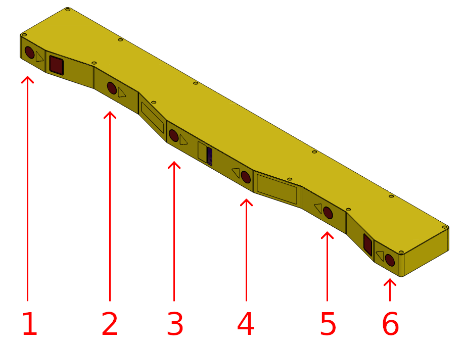
X6B
The JS-50 X6B features changes and improvements that distinguish it from the JS-25 X6B. Unlike the JS-25 X6B that has two mainboards internal to the design that require their own power and data connections, the JS-50 X6B has only one; eliminating the duplicated connections. The removal of the second mainboard also changes how the individual lasers are numbered. A diagram calling out the laser numbering is included below.