Network Settings
All communication to and from a JS-50 WX is done over an ethernet network through a UDP transport layer protocol. The details of communication to JS-50 WX devices is primarily managed by the Pinchot API; however, there are some considerations that the end user should be aware of.
Network Topology
The following network topology is recommended by JoeScan in order to avoid many common networking errors.

Generally speaking, the network should be set up such that all of the scanning devices are completely isolated from all other network activity. This means using an isolated NIC on the client computer and ensuring that the network switch isn't bridged over to any other networks.
Link Local IP Address
Using the above network topology will allow the scan heads and the network interface on the client PC to automatically network with each other using the Link Local software communication standard. This allows each of the devices to communicate on the same network without requiring additional server technology, such as DHCP, to assign IP addresses.
Testing Link Local
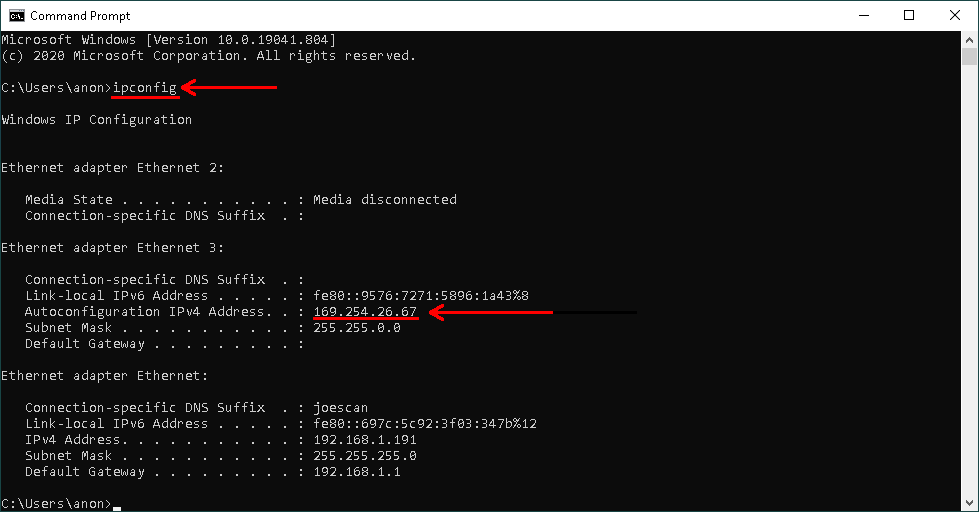
To ensure Link Local is working correctly on your system, the first step is to ensure that the wired network interface going out to the scanning network has a valid Link Local IP address. This can be doing using ipconfig in the Command Prompt and ensuring an IP address of the form 169.254.*.* is listed under the desired interface.
Once the client computer is confirmed to be properly configured, the next step is ensuring the JS-50 devices are configured properly. The ping command in Command Prompt can be used to see if the client PC can communicate to the JS-50 and determine if it has a Link Local IP address. Use ping -4 js-50-<SERIAL NUMBER>.local where <SERIAL NUMBER> is the serial number of the JS-50 to test connection; if ping succeeds and the JS-50's IP address is of the form 169.254.*.* then the system is configured correctly.

Troubleshooting
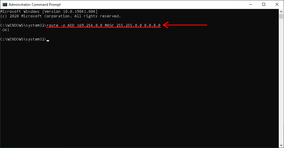
In the event that ping does not succeed or any of the JS-50 software applications fail to connect, one common fault on Windows is the routing table in the operating system not being configured such that it can send IP packets to a link local address. This can be addressed by running the following command route ADD 169.254.0.0 MASK 255.255.0.0 0.0.0.0 in Command Prompt. To make this routing change persistant, running the same command as administrator with the -p switch added can be done in Command Prompt, route -p ADD 169.254.0.0 MASK 255.255.0.0 0.0.0.0.
An example of setting a persistant route is shown below. First, the Command Prompt application is opened as an administrator by going to the Start Menu, finding the Command Prompt application, right clicking on it, then selecting Run as administrator.

Once Command Prompt has been started as an administrator, then the command can be run; success will be indicated by an Ok! message.
Network Optimization
Described below are approaches to increase networking performance for a given host computer interfacing with JS-50 scanners.
Hardware
For systems with multiple JS-50 devices or systems with high data throughput, the PoE Network Switch and Client Computer should both feature 10GbE network capabilities to allow maximum transfer speeds without loss of data. Using a standard 1Gbe network adapter with multiple JS-50s will cause the adapter to saturate and lose network data.
Windows
Increasing Network Receive Buffer Memory
For Windows host computers, increasing the memory of the network receive buffers will allow the host computer to queue up additional network packets when under heavy load rather than dropping them. This can be done by following the instructions below.
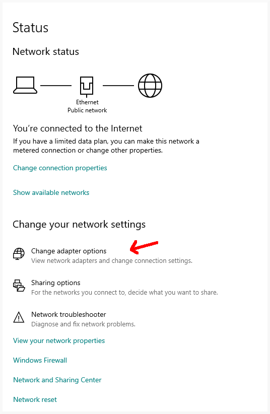
- Open Windows settings menu and select "Network & Internet".

- Next, select "Change adapter options".
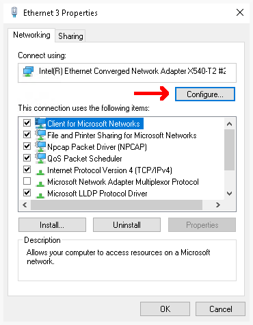
- Select the network adapter that is connected to the JS-50 devices and select "Change settings of this connection".

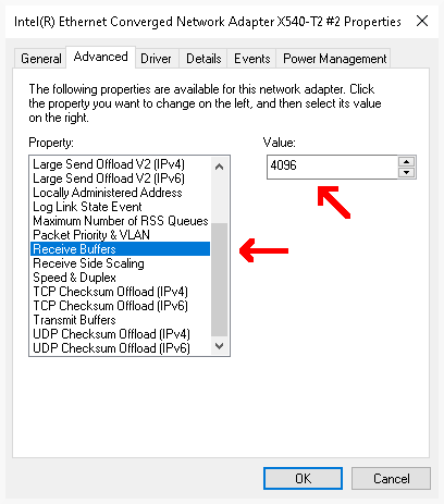
- Next, click the "Configure..." button.
- Navigate to the "Receive Buffers" property and increase the value to the amount of memory you wish to allocate to Windows to use for network buffering. The greater the value, the more memory will be used and the more packets that can be buffered.