JS-50 Configuration
The JS-50 has multiple configuration options that will influence how data is collected during scanning. These options will need to be determined and sent to the JS-50 using the Pinchot API before the start of each scan.
Scan Window
The Scan Window is a configurable region which can be used to exclude certain areas from being considered when scanning. Simply put, anything that is outside of the defined window will not be picked up and returned to the user from the API when scanning.
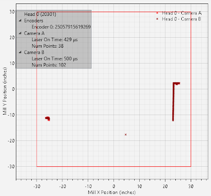
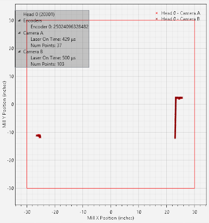
An example of SensorTester configuring the window is shown below. The first picture shows the window set to 30 inches in each direction.
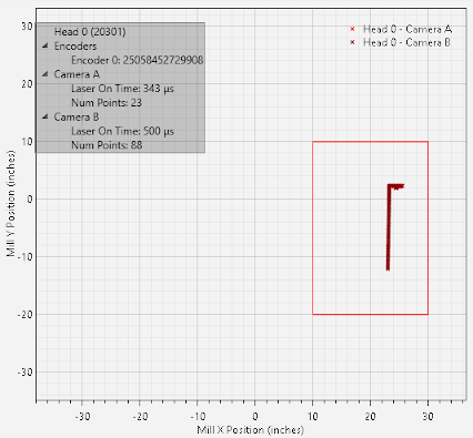
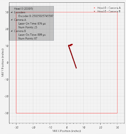
Using proper windowing, it's possible to filter out areas that would interfere with scan data. This example reduces the window to remove the far left feature.
Alignment Parameters
By adjusting the Align Parameters, it is possible to change how scan data is presented to the end user from each individual scan head. This is commonly used to have all of the scanning devices within a given system to have a common coordinate system that is referenced to the mill machinery; such as having Y axis be plumb vertical with Y = 0 set to the top of the chain and X = 0 being at the middle of the chain.
The following parameters are presented to the end user through the API.
Roll: Rotates the data by a specified number of degrees.
Shift X: Offsets the X axis by a given number of inches.
Shift Y: Offsets the Y axis by a given number of inches.
Cable Downstream: Flips the X axis in the event that a given JS-50 scanning device is oriented 180 degrees differently than other JS-50s within a system. This commonly happens if the orientation changes to facilitate better cable routing within a mill environment.
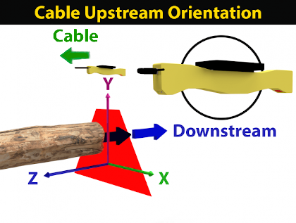
The default orientation of the JS-50 is shown below; this is referred to as being "cable upstream".
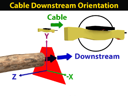
The orientation shown below has the JS-50 rotated about 180 degrees and is referred to as being "cable downstream". Note that the X axis for this orientation is mirrored from that of "cable upstream" shown above. Configuring the cable downstream option will correct this change such that it will instead have the same data coordinate system as cable upstream.
An example of changing the alignment parameters is shown below. First, a default alignment is captured.
The alignment parameters are then changed to offset the X axis by -20 inches and to add a roll of 20 degrees.
Scan Rate
The Scan Rate can be used to set the scanning frequency for an entire system of JS-50 scanning products. A higher scan rate will imply that data will arrive at the client computer faster relative to lower rates. The scan period, the numerical inverse of the scan rate, can be used to determine the amount of time that should elapse between each profile.
As an example, a scan rate 1000 Hz would imply that each JS-50 within a given system would be sending a new profile from one of the devices cameras once every 1 millisecond.
1 ÷ 1000 Hz = 0.001 seconds = 1 millisecond
Scan Offset
The Scan Offset can configure a JS-50 device to add a phase offset to its scanning such that laser crosstalk can be avoided between multiple scanning devices. This setting is crucial if multiple JS-50s are looking at the same region while scanning as without it, the lasers would fire at the same time and appear in each of the device's profile data.
Note that in order to ensure scanning synchronization across multiple JS-50s, a ScanSync will need to be installed within a given scan system.
Data Format
The Data Format can be used to configure the density of the scan data returned to the client PC from JS-50 scanning devices. The supported formats are the following.
XY full, LM full: full resolution XY data points and brightness measurements
XY half, LM half: half resolution XY data points and brightness measurements
XY quarter, LM quarter: quarter resolution XY data points and brightness measurements
XY full: full resolution XY data points
XY half: full resolution XY data points
XY quarter: quarter resolution XY data points
Exposure Control
Two different Exposure Controls are available to be controlled through software.
Laser Exposure: For XY and brightness profile data, this controls the amount of time the laser will remain on; the camera exposure time will automatically be calculated and managed by the JS-50 device.
Camera Exposure: When receiving image data, this controls the amount of time the camera sensor will remain exposed.
Additionally, the exposure can be to run with either manual exposure or auto exposure.
Fixed Exposure
Fixed Exposure will force the exposure to remain at a constant setting during the duration of a scan. In order to configure fixed exposure, the minimum, maximum, and default exposure settings should be configured to all be the same value. This value will define the constant exposure to be maintained.
Auto Exposure
Auto Exposure will allow the firmware on the JS-50 to dynamically adjust the exposure within a given range to try and achieve a desired result. To configure auto exposure, first define the bounds.
Minimum: The minimum exposure allowed.
Maximum: The maximum exposure allowed.
Default: The initial exposure value used.
Further, the following additional parameters are used to control the dynamics of auto exposure while scanning.
Laser Detection Threshold: Determines how bright a given camera region needs to be in order to trigger a valid data point. A lower value implies that data points will be generated with less light exposure and a higher value will require more light exposure for data to be generated.
Saturation Threshold: Sets the brightness required in order to consider a given data point to be considered saturated. Once enough points are saturated, auto exposure will then drive the laser on time down in order to reduce the number of points that are saturated. Similarly if not enough of the points are saturated, auto exposure will then drive the exposure time up.
Saturation Percentage: The percentage of data points returned within a given profile that are required in order to determine if the profile is sufficiently saturated. If over saturated this will engage auto exposure to drive the saturation down; similarly if under saturated auto exposure will then engage to drive the saturation up.