ScanSync
The ScanSync module acts as the master clock for the scanners in a system while also providing a means to communicate an attached encoder's relative position. All JS-50s on the same network will utilize the timing data from a ScanSync to synchronize their activities; this eliminates system timing issues that can occur if individual JS-50s are relying on their own internal clocks. This process is automatically performed and requires no intervention from the end user other than making sure that the ScanSync is on the same physical network as the JS-50 scan heads that are to be synchronized.
Note
The ScanSync module sends a continuous stream of broadcast data which can cause networking issues, especially with WiFi networks. It is highly recommended to keep the ScanSync module isolated to the scanning network.
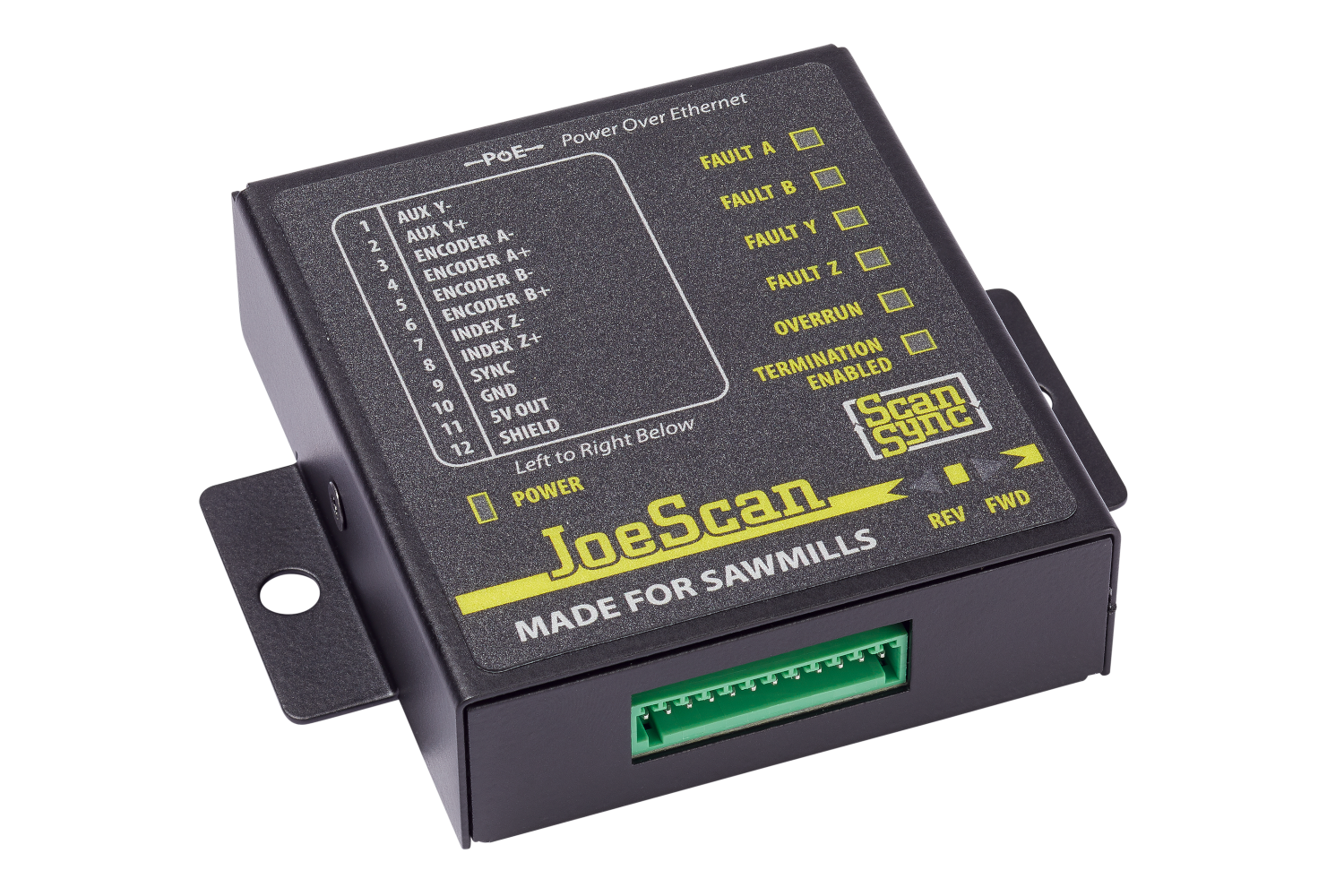
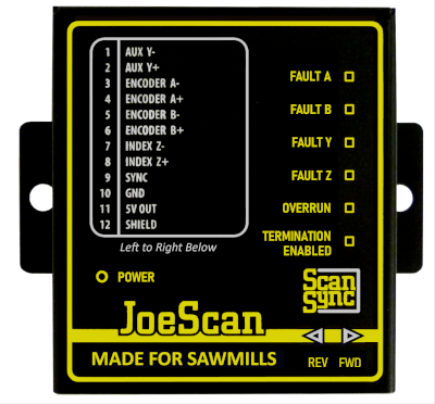
Status LEDs
The front panel of the ScanSync contains LEDs that indicate its current status.
| LED | Color | Description |
|---|---|---|
| Power | Green | Power over Ethernet (PoE) is present |
| Fault A | Red | Encoder A+/A- input connection is faulty |
| Fault B | Red | Encoder B+/B- input connection is faulty |
| Fault Y | Red | Reserved for future use |
| Fault Z | Red | Reserved for future use |
| Overrun | Red | Encoder data rate exceeds hardware capabilities |
| Termination Enabled | Yellow | Termination resistor pairs installed; used for long cables or high data transfer rate |
| Rev | Blue | Encoder is currently rotating in reverse direction |
| Fwd | Green | Encoder is currently rotating in forward direction |
Hardware Mounting
On the reverse side of the ScanSync enclosure is a DIN mounting bracket that can be used to secure the ScanSync onto a 35mm DIN rail.
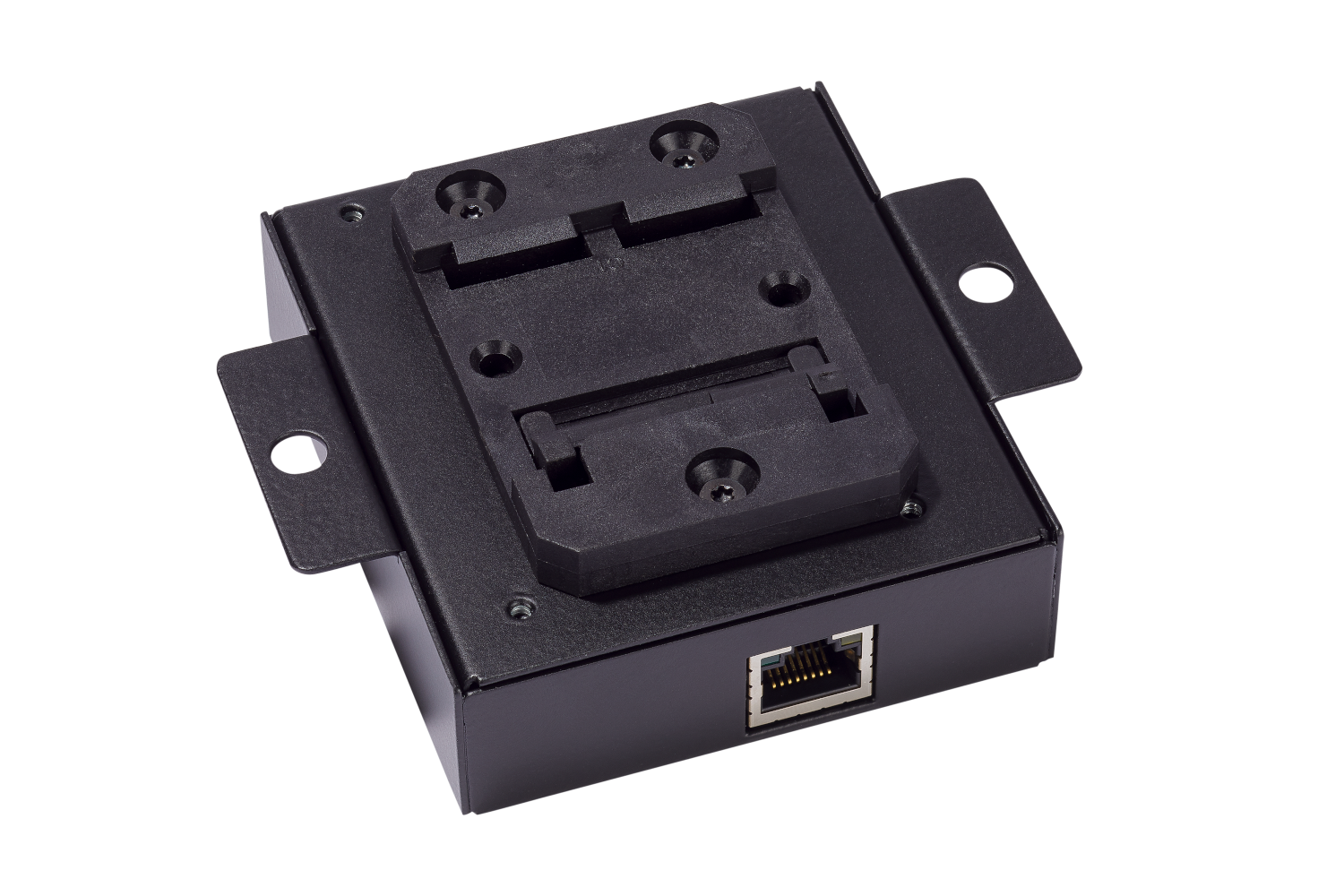
Electrical Connections
The ScanSync module has a 12 pin connector for the encoder and a PoE capable ethernet connection for networking and supplying power to the device.
12 Pin Connector
The 12 pin connector is used to connect the ScanSync to external inputs.
Note
Only RS422 5 volt differential output quadrature encoders should be used with the ScanSync.
| Pin | Connection | Description |
|---|---|---|
| 1 | Aux Y- | Reserved for future use |
| 2 | Aux Y+ | Reserved for future use |
| 3 | Encoder A- | RS422 quadrature encoder channel A- input |
| 4 | Encoder A+ | RS422 quadrature encoder channel A+ input |
| 5 | Encoder B- | RS422 quadrature encoder channel B- input |
| 6 | Encoder B+ | RS422 quadrature encoder channel B+ input |
| 7 | Index Z- | Reserved for future use |
| 8 | Index Z+ | Reserved for future use |
| 9 | Sync | 0-40V digital input |
| 10 | Ground | Electrical ground connection for RS422 encoder and Sync input |
| 11 | 5V Out | 5V 500mA power connection for RS422 encoder |
| 12 | Shield | Electrical shield connection for RS422 encoder |
Sync Input
As of ScanSync firmware version 2.0.3, support for the Sync input was added. The Sync input is a single ended digital input that can be used to connect a logic signal, such as that coming from a photo-eye, to the ScanSync. The signal should be between 0 and 40 volts in order to ensure proper functionality. The voltages and their corresponding logic states are described in the table below.
| Voltage | State |
|---|---|
| 0 - 6 | Low |
| 6 - 8 | Indeterminate |
| 8 - 40 | High |
Signals being routed into the Sync input should be either push-pull, being able to drive the line either to ground or Vcc without the need of an external resistor, or PNP / NPN switching output with either an external pull-down resistor (PNP) or pull-up resistor (NPN).
The logic state of this signal will be reported in the meta data provided with a given profile returned from the scan head. Refer to the C API or .NET API for specific implementation details.