ScanSync
The ScanSync module acts as the master clock for the scanners in a system while also providing a means to communicate an attached encoder's relative position. All JS-50's on the same network will utilize the timing data from a ScanSync to synchonize their activities; this eliminates system timing issues that can occur if individual JS-50's are relying on their own internal clocks. This process is automaticly performed and requires no intervention from the end user other than making sure that the ScanSync is on the same physical network as the JS-50 scan heads that are to be synchronized.
Note
The ScanSync module sends a continuous stream of broadcast data which can cause networking issues, especially with WiFi networks. It is highly recommended to keep the ScanSync module isolated to the scanning network.
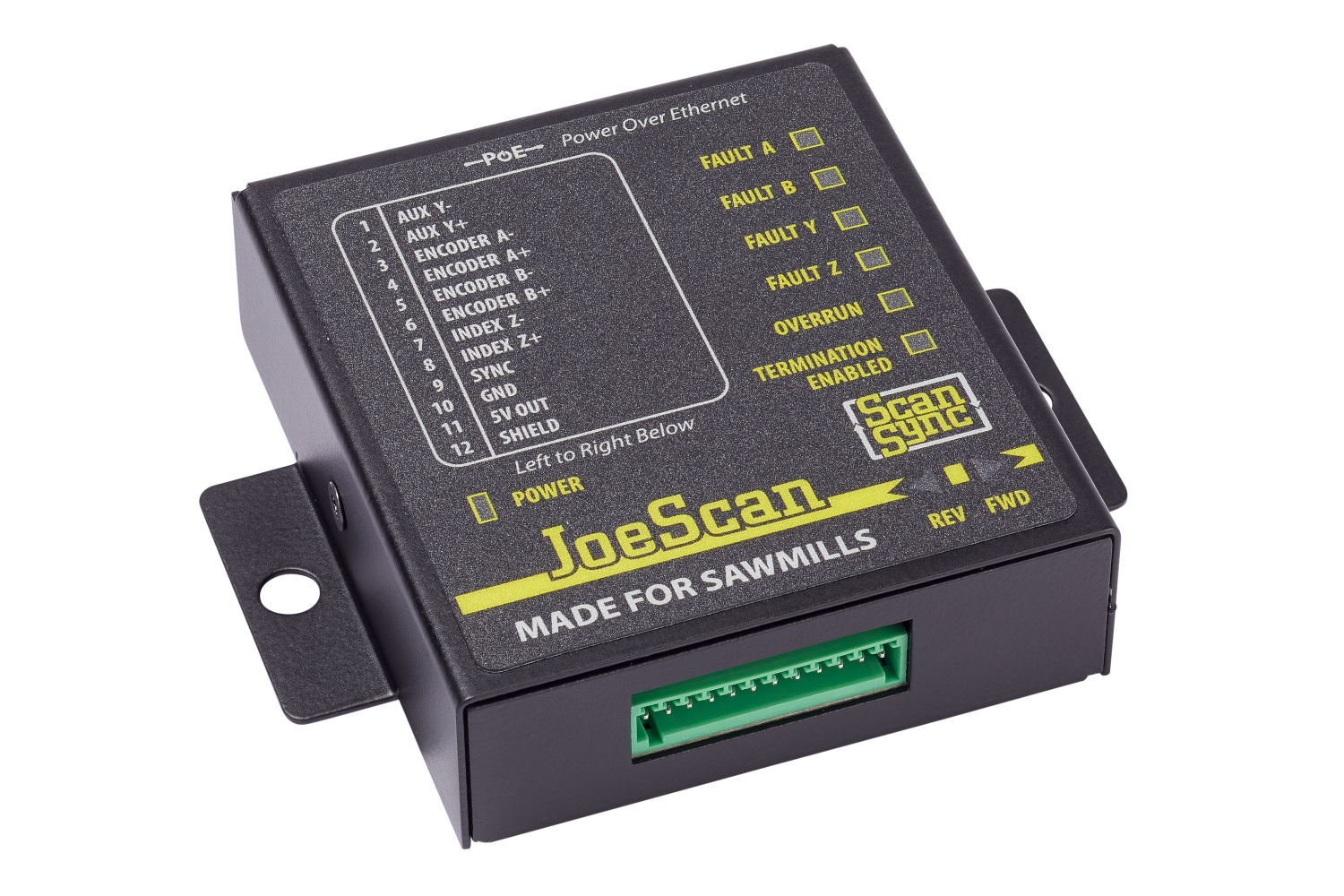
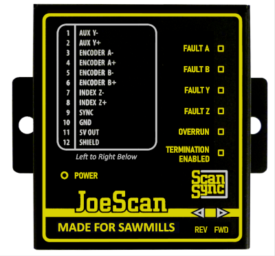
Status LEDs
The front panel of the ScanSync contains LEDs that indicate its current status.
| LED | Color | Description |
|---|---|---|
| Power | Green | Power over Ethernet (PoE) is present |
| Fault A | Red | Encoder A+/A- input connection is faulty |
| Fault B | Red | Encoder B+/B- input connection is faulty |
| Fault Y | Red | Reserved for future use |
| Fault Z | Red | Reserved for future use |
| Overrun | Red | Encoder data rate exceeds hardware capabilities |
| Termination Enabled | Yellow | Termination resistor pairs installed; used for long cables or high data transfer rate |
| Rev | Blue | Encoder is currently rotating in reverse direction |
| Fwd | Green | Encoder is currently rotating in forward direction |
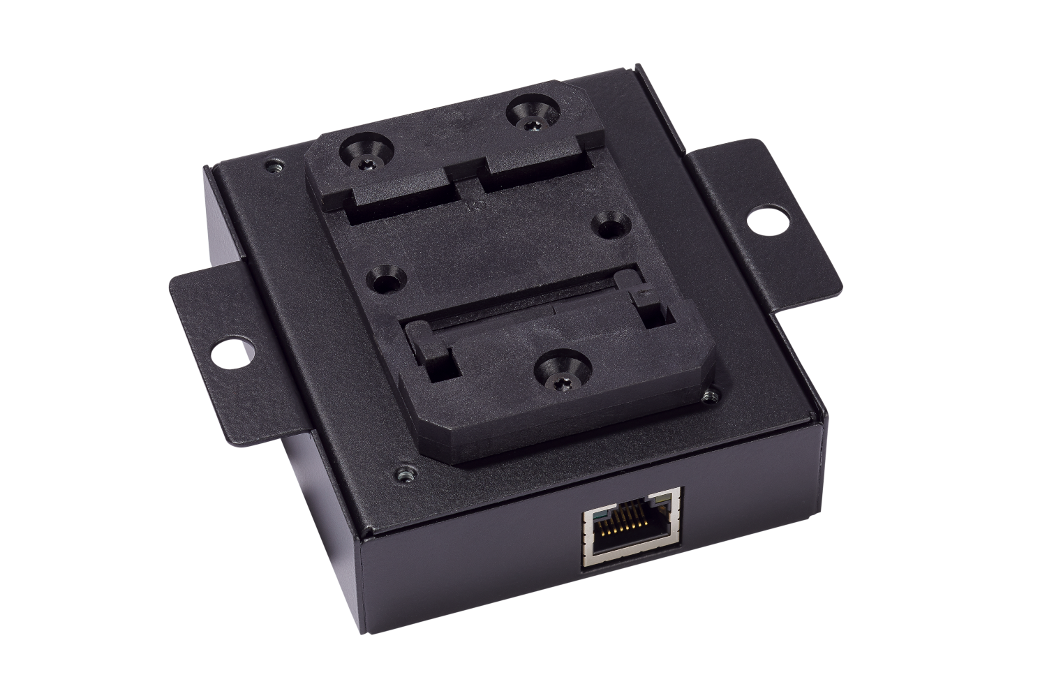
Hardware Mounting
On the reverse side of the ScanSync enclosure is a DIN mounting bracket that can be used to secure the ScanSync onto a 35mm DIN rail.
Electrical Connections
The ScanSync module has a 12 pin connector for the encoder and an ethernet connection used for networking and supplying power to the device itself.
12 Pin Connector
The 12 pin connector is used to connect the ScanSync to a RS422 5 volt tolerant quadrature encoder.
| Pin | Connection | Description |
|---|---|---|
| 1 | Aux Y- | Reserved for future use |
| 2 | Aux Y+ | Reserved for future use |
| 3 | Encoder A- | RS422 quadrature encoder channel A- input |
| 4 | Encoder A+ | RS422 quadrature encoder channel A+ input |
| 5 | Encoder B- | RS422 quadrature encoder channel B- input |
| 6 | Encoder B+ | RS422 quadrature encoder channel B+ input |
| 7 | Index Z- | Reserved for future use |
| 8 | Index Z+ | Reserved for future use |
| 9 | Sync | Reserved for future use |
| 10 | Ground | Electrical ground connection for RS422 encoder |
| 11 | 5V Out | 5V 500mA power connection for RS422 encoder |
| 12 | Shield | Electrical shield connection for RS422 encoder |
Ethernet
The ethernet connection on the ScanSync is used for networking data to JS-50 devices. Additionally, this connection is also used to provide power to the ScanSync by use of Power over Ethernet (PoE).
Networking
The ScanSync interfaces directly with JoeScan JS-50 devices over a common network and generally will only need to be interfaced with directly from a user's personal computer when performing firmware updates.
Note
The ScanSync should be connected to the same physical network switch as the JoeScan JS-50s that are desired to be synchronized.
IP Address
Like JS-50 scanners, the ScanSync will typically assign itself a link-local IP address in the absense of a DHCP server on the network assigning dynamic addresses. If a ScanSync is placed onto a network with a DHCP server, it will instead favor the dynamic IP address assigned to it.
Note
If the ScanSync is placed on a network without a DHCP server, the client computer will require a link-local IP address in order to communicate to the ScanSync.
Hostname
The ScanSync uses multicast DNS to assign itself a hostname that can instead be used to communicate over a network interface instead of the device's IP Address. For the ScanSync, it uses a hostname of the form scansync[SERIALNUMBER].local, where [SERIALNUMBER] is the serial number that is printed next to the 12 pin connector.
Below is an example using ScanSync with a serial number of 2864434397 to ping the device.
$ ping scansync2864434397.local
PING scansync2864434397.local (169.254.254.255) 56(84) bytes of data.
64 bytes from scansync2864434397.local (169.254.254.255): icmp_seq=1 ttl=255 time=0.193 ms
64 bytes from scansync2864434397.local (169.254.254.255): icmp_seq=2 ttl=255 time=0.118 ms
64 bytes from scansync2864434397.local (169.254.254.255): icmp_seq=3 ttl=255 time=0.119 ms
Firmware Update
In order to update the firmware on a ScanSync, the end user will need to access the ScanSync's web interface. The web interface provides the device's current firmware version and a simple dialoge to provide a firmware binary provided by JoeScan that can be used to update the ScanSync.
To reach the ScanSync's static web page, use a web browser and navigate to scansync[SERIALNUMBER].local.
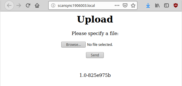
To upload a firmware file:
- Click the
Browse…button. - Browse to the binary file provided by JoeScan and select it.
- Click the
Sendbutton.
The ScanSync will then begin to update itself. If successful, the ScanSync will respond back with an OK message in the web browser and then proceed to reset itself. The new firmware version should be displayed in the ScanSync's web interface.